
Project DescriptionThis was yet another ME1770 project assignment. The objective was to simply create a small 3-D printed object. It was broken into portions- the sketch, CAD design, and 3D printing- each section was reviewed before moving on. For the individual project, I decided to model and create a custom heart locket. My idea inspiration rooted from my significant other whom had an upcoming birthday during the time. The locket is actually half of a heart (the other half would be mine in this case). I saw as something not too difficult and not too simple; and so I took the project on. The design is composed of three components: One half of the half, which would hold the picture, the other half that acts as the “lid”, and the rod to allow the halves to move on its hinges. I used the traditional peg and hole system to act as the “lock” to the locket. I also included an extruded piece for a chain to fit through so that it could actually be a wearable piece of jewelry.
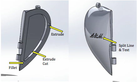
CAD designs with required features identified
Manufacturing
In the making of this project, I did some research on a few heart locket designs 3D printed and those out of jewelry stores to compile my own design. The peg and hole locking system is the traditional theme for locking, or securing, the halves of the locket together. I positioned the peg in a place where it wouldn’t potentially get damaged or interfere with the remainder of the part. Also, in making the peg, I had to consider the position of the hole, which would have to go through the half. The goal was for the hole not to be seen from the outside.
While 3D printing, I tried to make the belly of the half of the hearts simplistic for easier removal, which was true. The back (the curvature) could have potentially been easier in removal of the trimmings. I anticipated that there could be problems with the peg in the peg and hole system as well as he hinges in the removal of the trimming. I tried to add as much as support in the design as I could to ensure more careful removal. |

Heart Locket Sketch/Concept
Cad FeaturesTo create the halves of the half of the heart shape, I used a loft. After, I made a extrude cut to make an indention in the object for a picture to fit comfortable into. From there, I used fillet to smoothen out the sharp points to give it a more gentle, desirable look, as well as for safety reasons. I filleted the extruded cut portion, as well as the outside points and corners. From there, I performed another extruded cut to make a dip on the side where the hinges would go so that they still slightly aligned with the shape and would be more secured in the object. I used fillet to smoothen those edges out as well. I used the extrude feature to make the peg for one half. Before adding anything else, I used the body move/copy feature to copy the half I created and make the other half. To make the hinges, I used extrude and extrude cut to hollow it out for the rod. The hole for the peg was created using extrude cut in the shape of the peg (the hole had to be a little deeper and wider for tolerance). The part for the chain to feed through was made using extrude and extrude cut as well. The words that are embedded in the half was created using split line and text. The rod was a simple extrude.
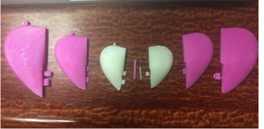
Failed attempts (final in the white)
Challenges
The 3D printing process was smooth for the most part. My part always came out smoothly. It was scale and removing the excess material that gave me a lot of trouble. Upon entering the studio for the first time, I used my actually project as the test part. That’s when I discovered that I should scale it down. I researched the size of a typically locket and did some quick calculations to get an idea of the range I need to be in. It took three attempts to get it to a comfortable size for the locket. There was one fail print, but it didn’t take long to reprint. I had to go back on SOLIDWORKS and rework my design to fix the support on the hinges, the alignment, the peg hole tolerance, and the tolerance for the rod. I found out through each print (despite the scale issue). I found out that my hinges needed more support during the process of removing excess material and two fell off. I tried to make them stable, but the final design still had risky hinges. With enough pressure, it could possibly snap. The rod issue never truly got resolved. I ran out of time to reprint before fixing the tolerance. The peg and hole issue got resolved with about .2/.3 tolerance on the hole and peg. Tolerance was a big issue for me. Despite some input I received from peers, it appears that for smaller items it’s a tad different situation. Also, the text never printed, which makes me question the selectiveness of text with 3D printing when using SOLIDWORKS.
After completing the individual project, I’ve learned that you can create anything as long as you’re willing to take the time design, create, fail, and repeat. My locket was not a success, but through the first failure to the last, I learned more about SOLIDWORKS, 3D printing (methods and tricks to printing), and the process of designing and manufacturing. Through the 3D printing process, I’ve learned about tolerances and how they can vary from object-to-object based off of scale and other factors. My evolved in scale, strength, and color from the initial state. With more time, I’m sure I could have produced the locket I dreamed of. |
